How Do You Choose the Right Bore Gage?
Selecting the correct bore
gage begins with knowing as much as possible about your application.
By Denis Newton
& Fred V. Fowler III
Bore
gaging, already a significant factor in manufacturing, has become
increasingly important in metrology because of the growing concern
for total quality assurance (TQA). Compared with outside-diameter
(OD) measurement, bore gaging creates more engineering challenges
by the very nature of its special role in QA. This is especially
true when measuring difficult-to-assess internal features such as
splines, threads, and deep bores.
As machine capability
increases, so does the demand for dimensional gaging to cope with
tighter limits on tolerances and greater complexity of component
parts. Some manufacturers are not so much concerned with making
the component to a specific tolerance band as they are with size
variation from component to component. This gives them better control
of their process, but it also means that the gage they use must
be able to discriminate size variation better than before.
Many manufacturers now
require that any in-process or post-process gage record and send
the measured size of a component to a statistical process control
(SPC) or data collection system.
Making a gage choice
In choosing a bore gage,
begin eliminating those types of bore gages that are least appropriate
for a production environment. Noncontact measurement techniques,
including optical and laser methods, tend to be bulky, relatively
expensive, and inflexible when measuring special internal features.
Such gaging requires the part to be taken to the gage. Not all types
of noncontact systems are suitable for a production environment,
and many entail high maintenance costs.
Coordinate measuring
machines (CMM) are occasionally found in production situations,
but many are expensive and they can be relatively slow. Parts cannot
be checked while in the machine. CMMs also have high initial and
maintenance costs.
Another gaging method
is the use of plug gages. However, plug gages do not allow for electronic
data collection for SPC systems. Each plug gage is suitable for
only one specific bore size, and it has no working range. It only
confirms if the part is good or bad and cannot identify subtle drifts
of component size variation within the tolerance band. As it is
both the reference master and the working gage, it is subject to
wear, and there is a subsequent cost for recalibration or replacement.
Two and three-point contact
measurement is a popular solution as a production gage and provides
many options. The gage is typically calibrated to a reference master,
such as a setting ring, which means that only the setting ring itself
must be calibrated regularly. For this reason, the reduction in
operating costs compared to pin or plug gages is significant. Depending
on the type chosen, gages under this description can have a wide
working range. Moreover, they offer the best flexibility for adaptation
to special feature measurement. Both two- and three-point contact
methods can measure deep into bores, have lower initial and maintenance
costs, and are portable. Digital versions can interface with SPC
systems.
Two- and three-point bore-gage options
After a manufacturer
has made the decision to use a bore gage for his application, there
are still some choices to be made among the use of various two-
and three-point devices.
Cylinder bore gages.
As the name suggests, this gage was originally developed to measure
cylinder bores in the automotive industry. It is a two-point contact
measuring system for use on components that may be subject to ovality
problems. The design includes a mechanism to centralize the measuring
head in the bore. It is a cost-effective solution for simple bore
measurement and can be easily adapted to measure bores up to 6 feet
deep.
There are several cylinder
bore gage limitations. There are many on the market with very poor
linear accuracy. They have to be calibrated exactly at the size
being checked. When purchasing a cylinder bore gage, always ask
for the specification on linear accuracy.
Cylinder bore gages are
not easily adapted to measure special features and require multiple
setting masters. Analog versions require the operator to decide
when he has established the minimum value, which can introduce variability
from operator to operator. Unless a definite tendency towards ovality
exists in the manufacturing process, a three-point system is a better
solution.
|
Special applications
The following examples are a selection
of the special, or nonstandard, applications that can be handled
by two- and three-point bore gaging systems:
Threads. Threads down to 4
mm or 0.160 inch can be checked. Thread forms of UN, (UNC,
UNF, UNJ, UNS) Metric, Acme, Whi2rth, Buttress, BSP, BA, BSF,
and PG, in both standard and nonstandard pitches, can be measured
in either left- or right-hand form.
Splines. Spline measurement
is normally carried out with a two-point head, whether there
is an even or odd number of splines.
Deep bore measurement. Use
a measuring head equipped with an internal transducer to measure
anvil movement. Activation of the gaging force is achieved
via a pneumatic cylinder inside the measuring head. The measuring
anvils have a spherical form that results in an accurate reading,
even if there is misalignment of the measuring head relative
to the axis of the bore. The operator activates the gaging
force via a foot switch and reads the bore size on a digital
display unit, resolving down to 0.00001 inch and 0.0001 mm.
|
Micrometer bore gages.
The traditional internal micrometer has many advantages in its flexibility,
offering a choice of two- or three-point systems, a large working
range on each measuring head, and adaptability to measuring special
features. Depending on which design is chosen, it is possible to
find systems that can measure from 0.040 inch to 12 inches as a
standard range. Both analog and digital versions are available,
with the digital available as either mechanical or electronic. Only
the electronic versions have the ability to send data to an SPC
system, printer, or data collector.
Some manufacturers also
offer a wide range of options, where features such as threads, splines,
grooves, ball race, ball nuts, and bores as deep as 80 feet can
be measured. Micrometer bore gages have to be calibrated to a setting
ring. When selecting a gage, be aware that not all manufacturers
include the cost of setting rings in their prices. This can make
a considerable difference to the final purchase price, particularly
if a calibration certificate is required with the setting ring.
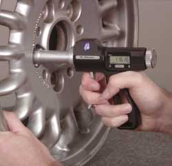
Pistol-grip bore gages.
This gage type offers all the advantages of the traditional internal
micrometer, and it allows a fast, single-handed operation. The fact
that there is a constant gaging force, independent of operator "feel,"
with the pistol-grip bore gage facilitates good gage repeatability
and reproducibility results. It is very adaptable to measuring special
features such as spline pitch diameter, ball races, and ball nuts.
To decide whether to
choose a two- or three-point bore gage, it is important to understand
the advantages and disadvantages of these two systems. The choice
between two- and three-point systems centers around what type of
geometry your manufacturing process generates, because no bore is
perfectly round.
The effect of lobing
In an instance where
a two-point bore gage system collects the absolute minimum and maximum
values in an oval bore, there may be a limitation when the two-point
system is used on a bore with a trilobed form. In such a case, the
two-point gage could give the same value of bore size even if the
bore was checked in several positions. It misses both the absolute
minimum and maximum bore sizes.
In the same instance,
the three-point system shows its limitations when checking an oval
hole because it cannot capture the absolute maximum and minimum.
However, the correct minimum-maximum values are established when
the three-point system is applied to the trilobed hole.
Most holes are neither
truly oval nor perfectly trilobed, but are more a series of lobes
of varying magnitude. The three-point system is the solution for
the majority of cases because it offers the best "average" result.
The only case when this is not true is where there is a definite
tendency toward ovality within the manufacturing process.
It is very imortant to
remember that bore gages do not measure geometry. The only correct
way to establish what type of condition your manufacturing process
generates is to measure a series of components on a roundness-checking
device. From this, one can deduce whether a two- or three-point
bore gaging system should be used.
ami
|