|


LINEAR ENCODER SPECIFICATIONS
| ENCODER |
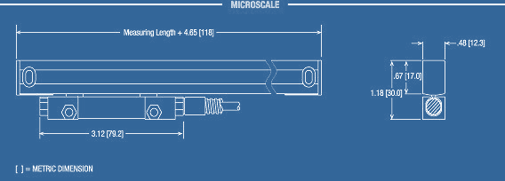
MicroScale
|
| Resolution |
0.5µm
(.00002")
|
1µm
(.00005") |
5µm
(.0002") |
Accuracy (at20° C)
µm, ±, in any 50mm(2')
µm, ±, in any 250mm(10')
µm, ±, in any 1000mm(40') |
1.5
3.0
5.0
|
1.5
3.0
5.0 |
3.0
4.0
5.0 |
| Signal Output |
Digital |
| Scale Principle |
Optical/Glass |
Maximum slew speed (in/sec)
at 0° C to 40° C |
40 |
Operating Environment
Temperature
Humidity |
0° to 40°C
25% to 95% (non-condensing) |
| Cable Material |
Nickel-plated Armor
or Vinyl |
| Cable Length |
2, 5, 10, 15, 20 ft |
| Maximum Cable Length (ft) |
36 |
| Measuring Lengths (in) |
1-60" |
| Reference Mark Interval |
100mm |
| Endcaps |
Sealed
Die Cast |
| Sealed Reading Head Electronics |
Yes |
| Lipseal Material |
Recessed
Interlocking
Fluoroelastomer |
|
ELECTRICAL
SPECIFICATIONS
|
Digital
|

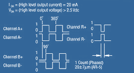
IOL = (Low level output current) = -20mA
VOL = (Low level output voltage)< 0.5Vdc
|
|
Light Source
|
LED (Light-emitting diode)
|
|
Operating Voltage (VDC)
|
5.1 ±0.1
|
|
Operating Current (Max. mA)
|
140
|
|
Differential Output Signals
(incremental) (TTL)
|
Two square-wave voltage
signals, channels A and B, in 90° quadrature relationship
|
|
Reference Mark
(TTL level)
|
One square-wave pulse
|
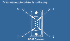
| DIGITAL
PIN-OUTS AND OUTPUT SIGNALS |
|

|
| DE
Pin |
Signal |
DE Wire Color |
| 1 |
No Connection |
|
| 2 |
Channel A + |
Green |
| 3 |
Channel A - |
Yellow |
| 4 |
Channel B + |
Blue |
| 5 |
Channel B - |
Red |
| 6 |
Ground (power supply and signal
return) |
White |
| 7 |
Supply Voltage |
Brown |
| 8 |
Channel R + (Reference Mark) |
Pink |
| 9 |
Channel R - (Reference Mark) |
Gray |
| |
Shield |
Drain |
|
