Calibration
Internal ISO Quality Systems
Our
quality system has established lines of management
control with defined levels of responsibility to
assure the effectiveness of our policy. We employ
the best talent, machinery, and inspection equipment
for our manufacturing lines. This builds and
coordinates a high quality atmosphere to ensure
customer satisfaction. Together as a “TEAM”,
Universals management team and employees are
strongly committed to delivering only the best
quality product; “ON TIME” and “EVERY TIME".
ISO
9001:2000 Certified: The scope of Machining and
Packaging of Medical Components and Instruments.
ISO 13485:2003 Compliant: The scope of Machining and
Packaging of Medical Components and Instruments.
FDA Compliant to FDA part 21 CFR 820 for the scope
of Machining and Packaging of Medical Components and
Instruments.
12.0
Calibration
12.1 Purpose
To establish a
standard procedure for the calibration of all
Concentricity Gages.
12.2 Scope
All Concentricity
Gages used to measure, test, inspect, or otherwise
examine items to determine compliance with set
specifications. This procedure also applies to Gages
returned to Universal Punch Corp. for routine
calibration.
12.3 Definitions
Calibration
– A procedure performed under specific conditions that
establishes the relationship between values measured and
known values derived from applicable standards.
Recalibration
– A systematic check and adjustment of the accuracy and
precision of a particular item performed at prescribed
intervals.
Verification
– A check for proper “zero” and limited confirmation of
an items accuracy by comparing it to a known standard.
Runout
- (Measured in Full Indicator Movement or “FIM”) – The
measurement of surface variation that occurs relative to
an axis of rotation. It is the total amount of movement
(FIM) on an indicator after on full revolution of a part
that is rotated about its datum axis. It may be measured
parallel (outer surface) or perpendicular (face) to the
axis.
12.4 Materials and
Conditions required
Granite Surface Plate
with floor vibration isolators
Calibrated gage Test Pin traceable to N.I.S.T. (size
depends on Gage being tested)
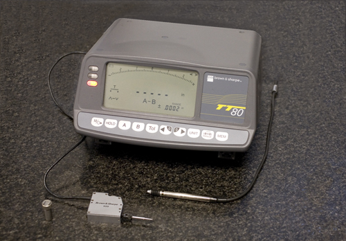
Electronic Gage Head or Gage Probe (LVDT) with Amplifier
at 10:1 ratio
Cleaning solution and Lint-free Cloth
Temperature controlled environment at ±2° with ½° change
per hour.
12.5
Special precautions
Verify that the
calibration status of all equipment being used is
current.
Do not use abrasive stones to remove imperfections on
the Gage Roller surfaces.
Use caution when removing dirt, oil and other foreign
substances when cleaning Gages.
12.6 Tolerances (Runout)
12.6.1 .0002” Max. for
standard Gage assembly (Black Models)
12.6.2 .000070” Max. for precision Gage assembly
(Gold Models)
12.7 Procedure
Verify that the
identification on the Gage is distinct and in agreement
with the Calibration History or the customer PO number.
(New Gage / Recalibration).
Carefully examine the
Main Rollers and the Top Roller for nicks, burrs, rust
or other signs of mishandling or wear. Replace the Main
Roller or Top Roller if necessary.
Carefully clean all
exposed surfaces removing all foreign substances and
particulate matter.
Move the Indicator
Carrier to the right to provide sufficient clearance to
insert the test pin into the Gage without interference.
Using the appropriate
holder, mount the measuring instrument to the Indicator
Carrier holder on the Concentricity Gage. Ensure that it
is properly placed and rigidly held by the Holder /
Indicator Carrier assembly.
Verify the runout to
be measured and place the appropriate calibrated test
pin into the Concentricity Gage between the Main Rollers
and allow the Top Roller to clamp it securely.
Move the Indicator
Carrier holder with the measuring instrument assembly
and bring the measuring instrument into position to
measure the Calibrated test pin. This is a point
approximately ¼ “ from the end of the Main Rollers
aligned with the centerline of the test pin in the
vertical direction as shown in Figure 15a.
Zero the measuring
instrument according to the manufacturers instructions.
Using the drive system
of the Concentricity Gage, rotate the test pin a minimum
of three revolutions to establish seating in the Main
Rollers. Rotate the Drive Knob slowly and note the
readings (FIM) from the measuring device.
Repeat Rotation
a minimum of 3 times to rule out any obvious incorrect
readings.
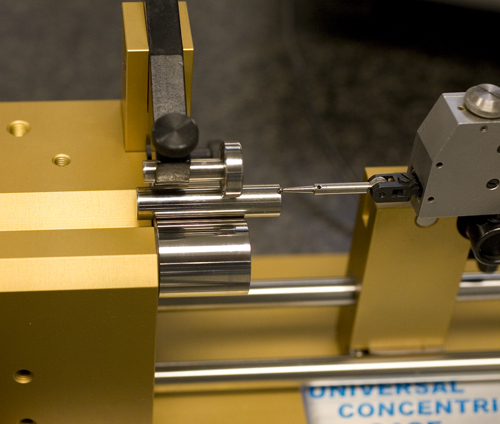
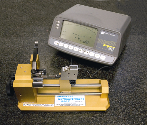
Figure 15a. Calibration Set-up. Model
B-10 shown.
Storage and Handling Active and inactive equipment shall
be maintained, stored and handled in such a way as to
preserve its accuracy and fitness for use. Equipment
that is out of calibration or damaged shall be removed
from use.
Calibration Proceedure Document |
